Our Products
Discover BioSpherix’s extensive range of innovative products designed for biomedical research and clinical applications, including our dynamic environmental controllers that can precisely regulate O₂, CO₂, temperature, humidity, and even ammonia in real time. Our physiologic incubator subchambers provide isolated, independently controlled microenvironments to simulate true in vivo conditions within a shared incubator space. At the heart of our business is the flagship Xvivo System®; a modular, closed, GMP-compliant cell culture platform engineered to deliver reproducible, physiologic conditions for advanced cell manufacturing. All of our products deliver Cytocentric® environments for optimal cell care.
View our product manuals and technical documents
Visit our YouTube channel for maintenance how-to’s and product demonstrations
Learn more about the funding options specific to your project.

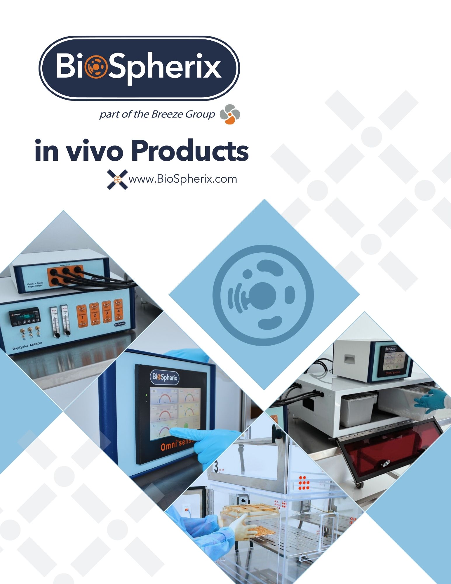
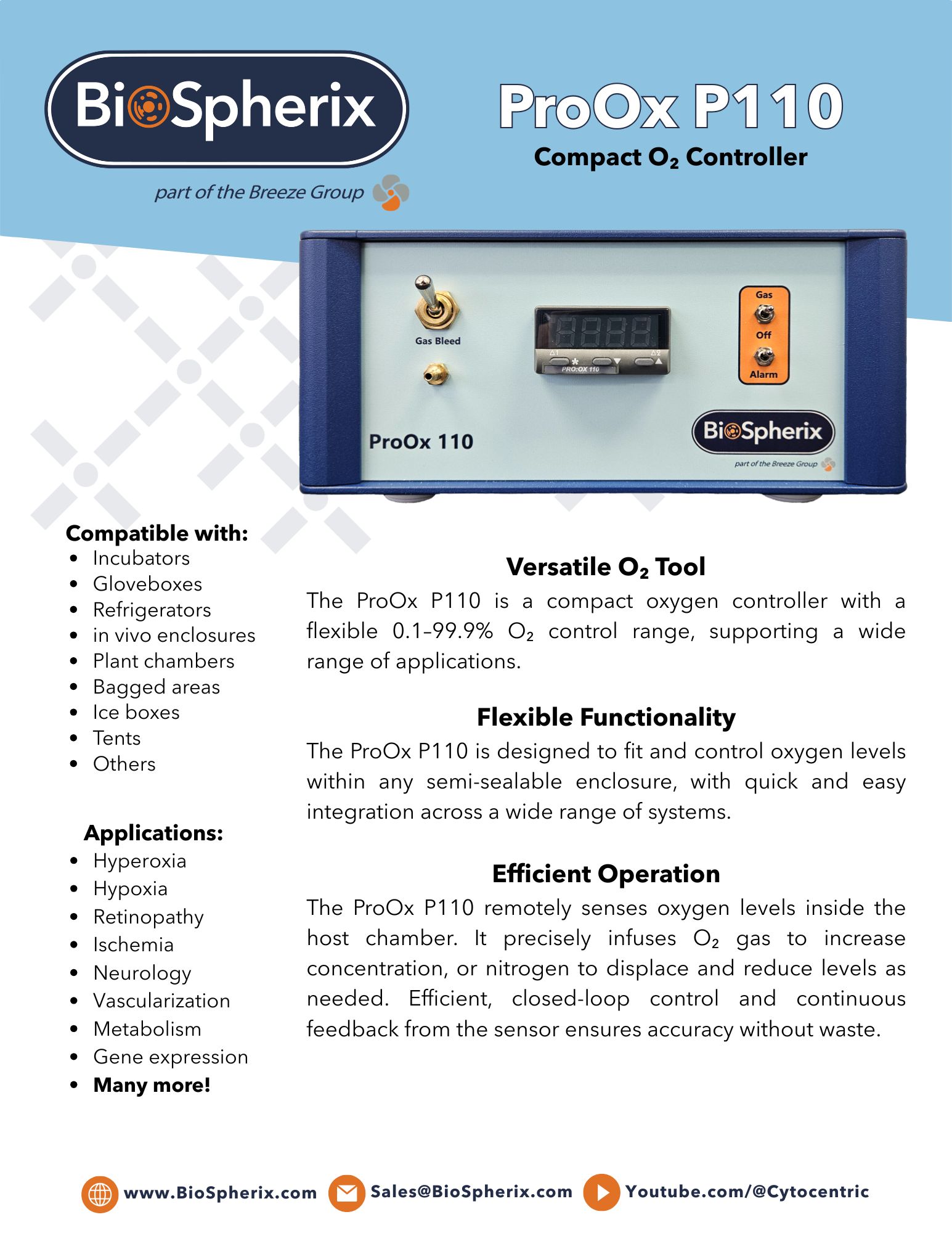
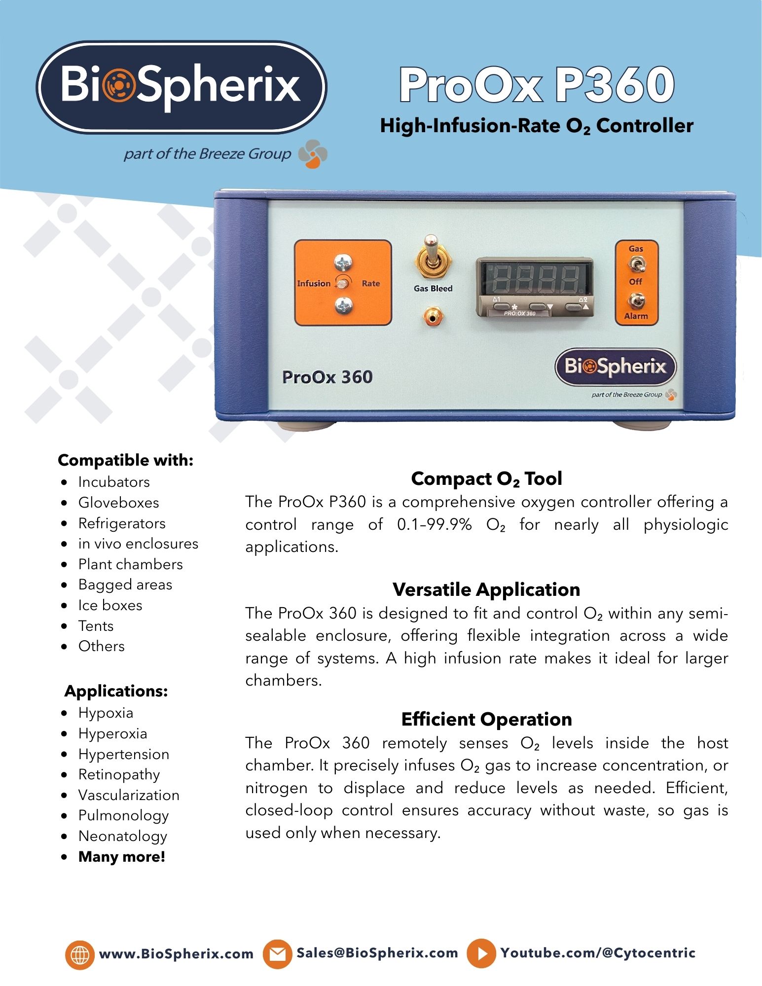
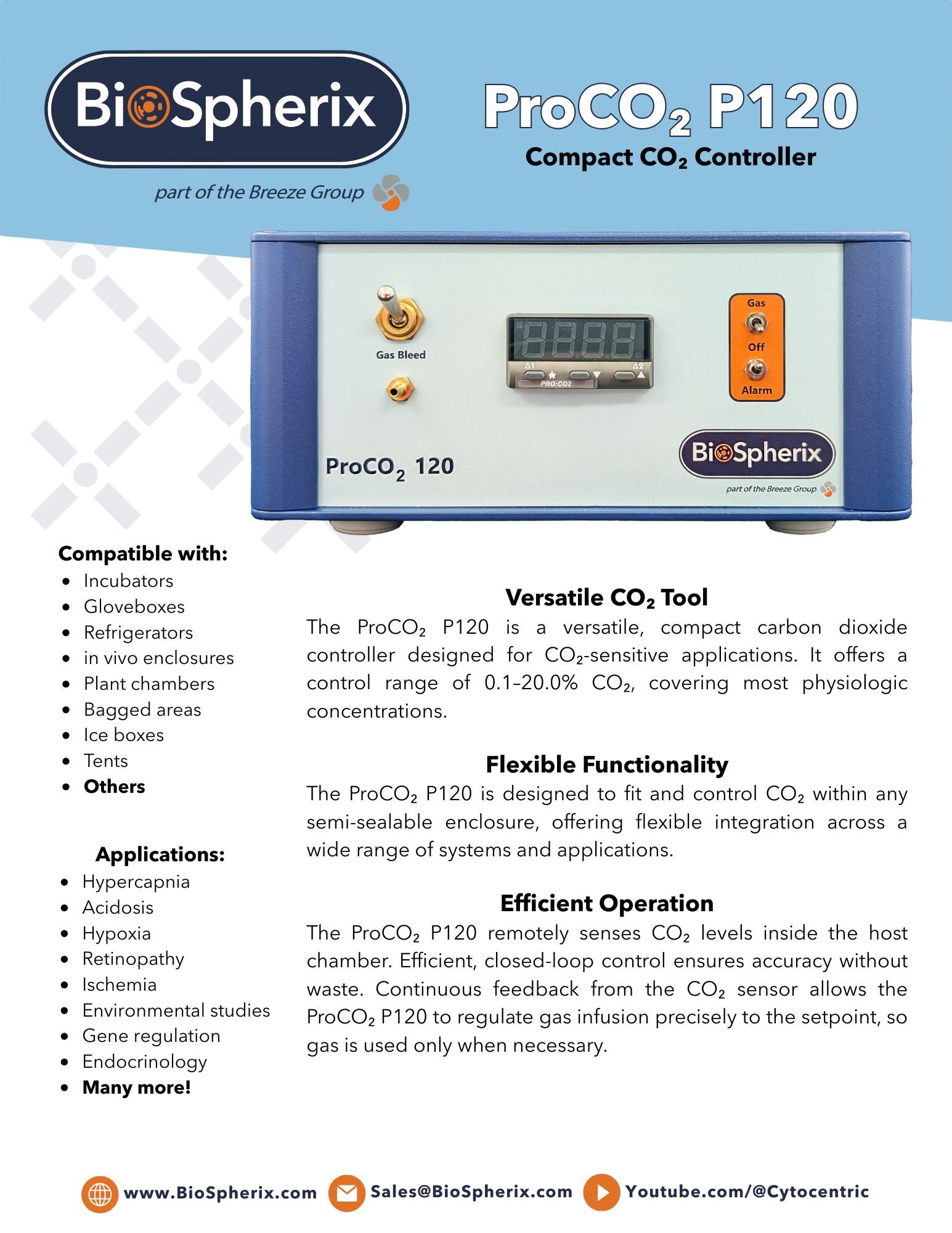
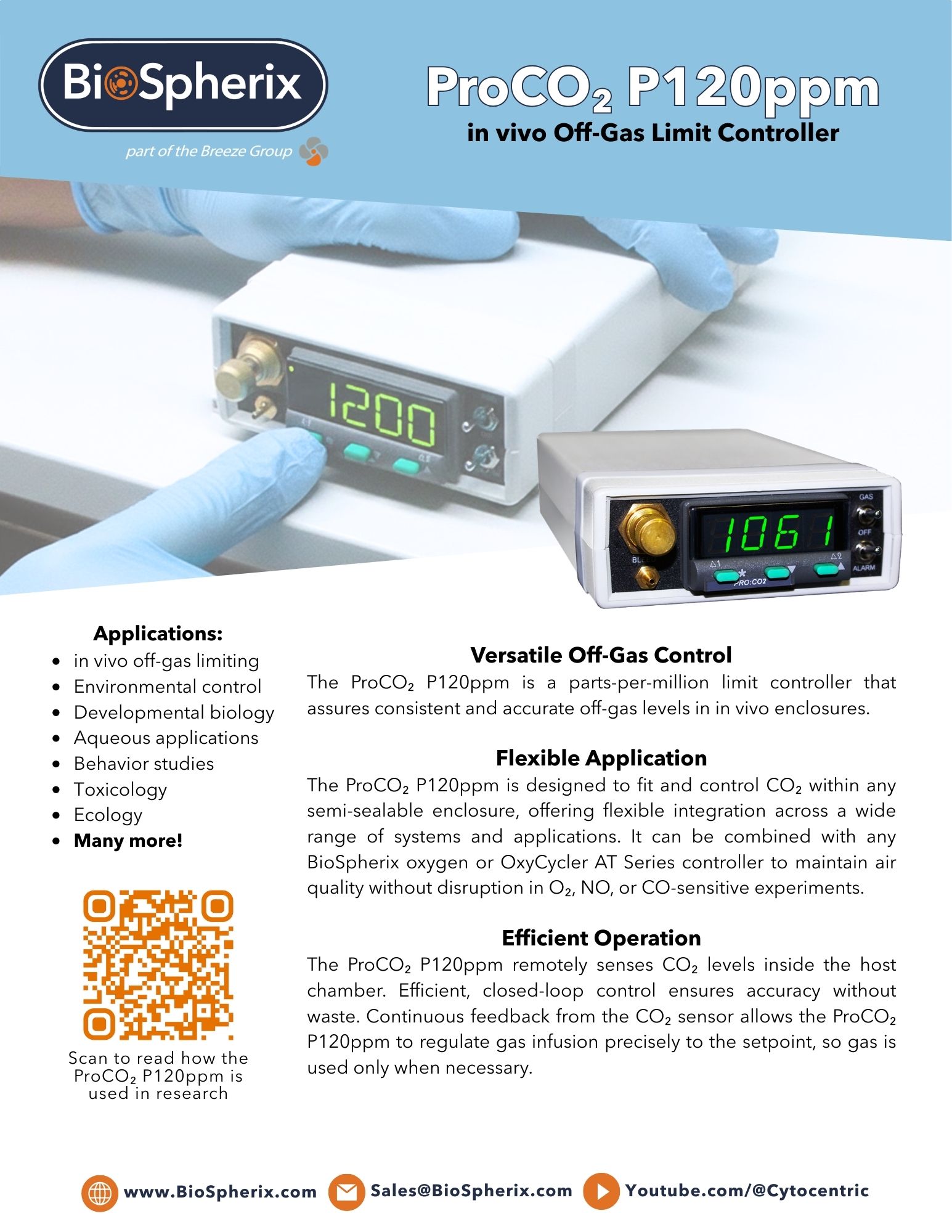
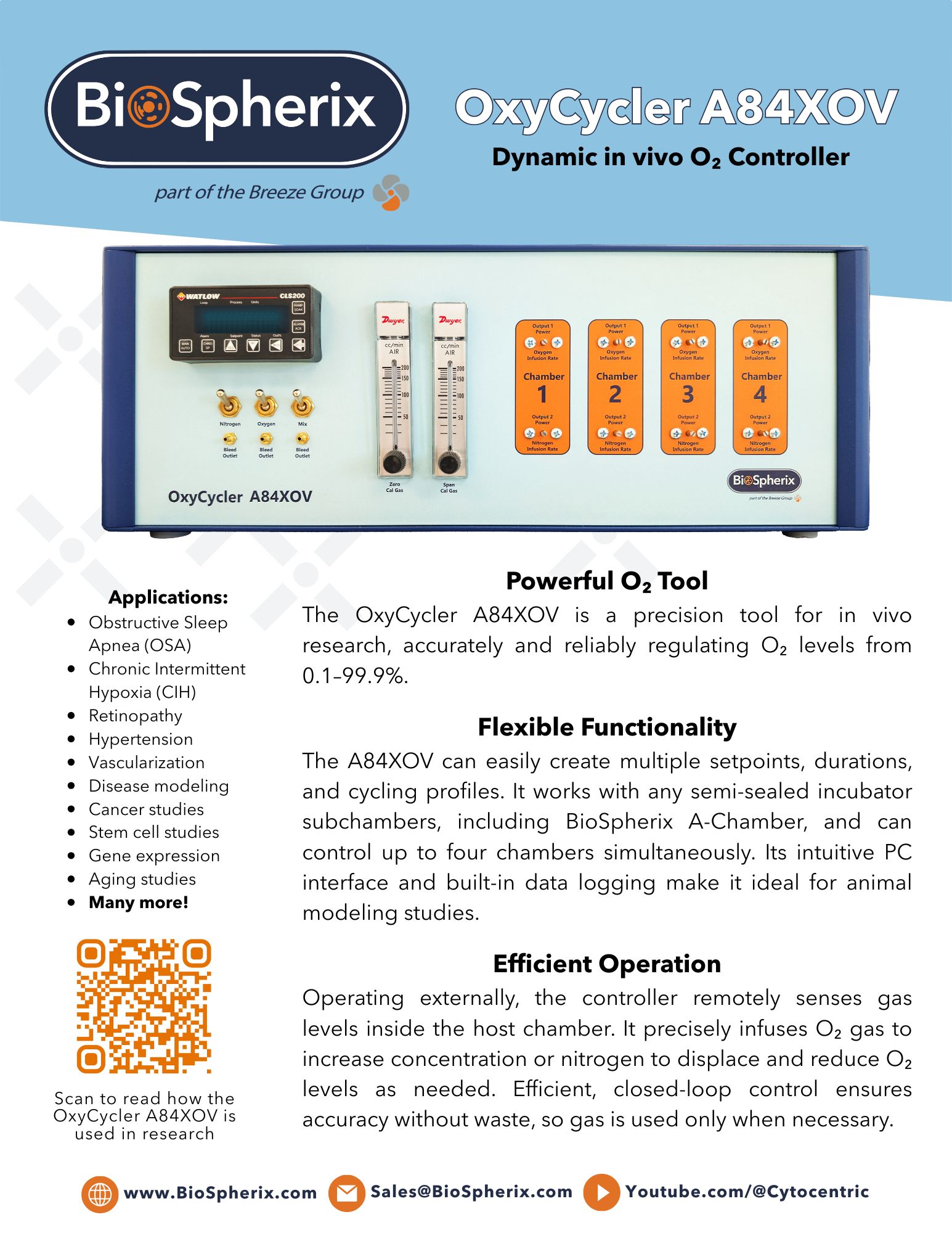
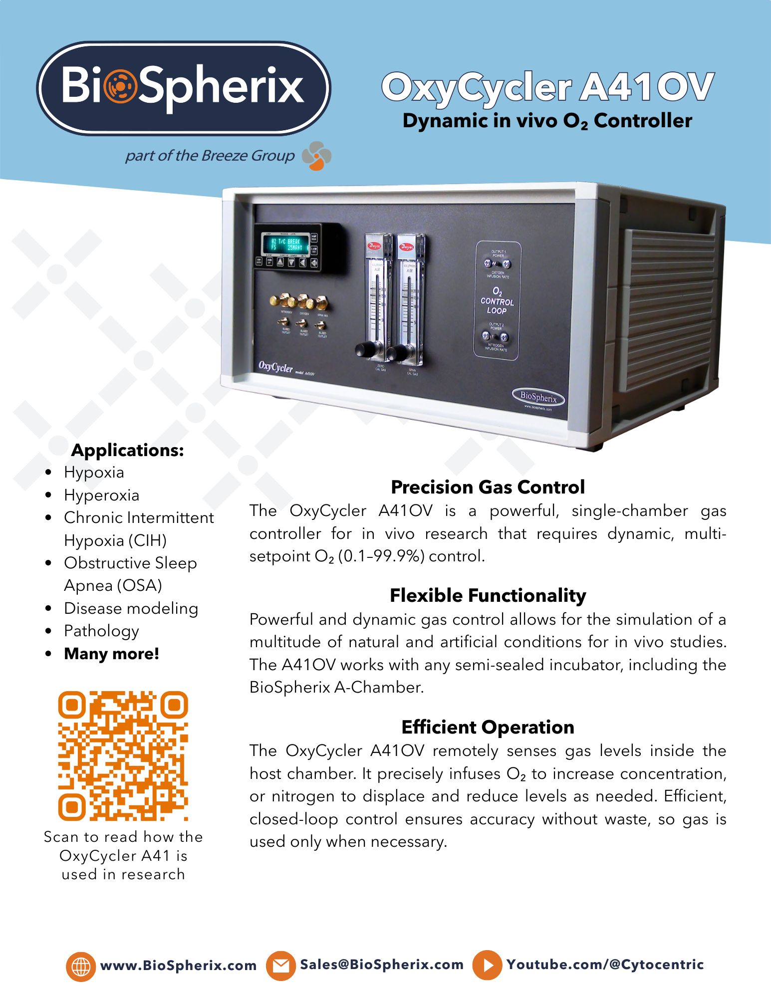
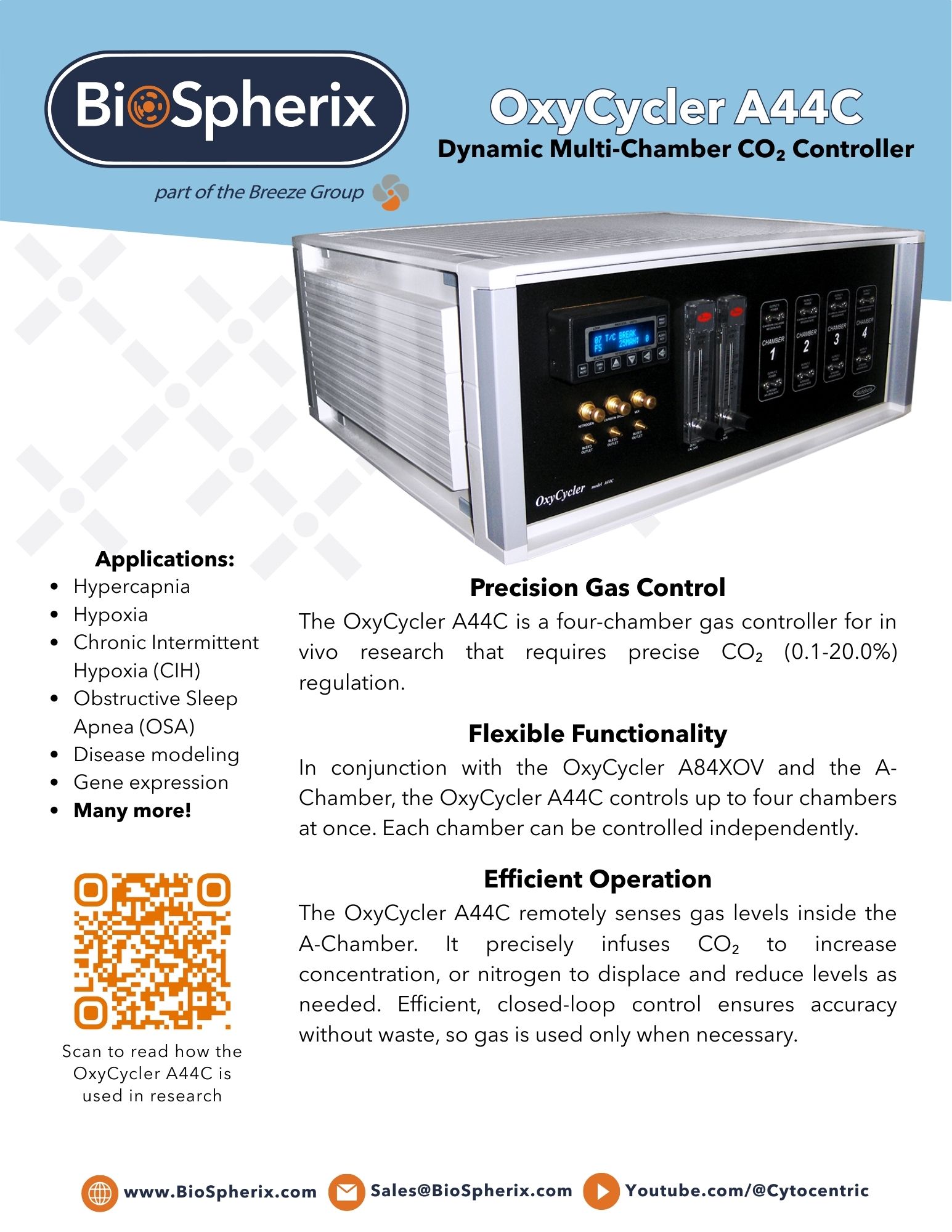
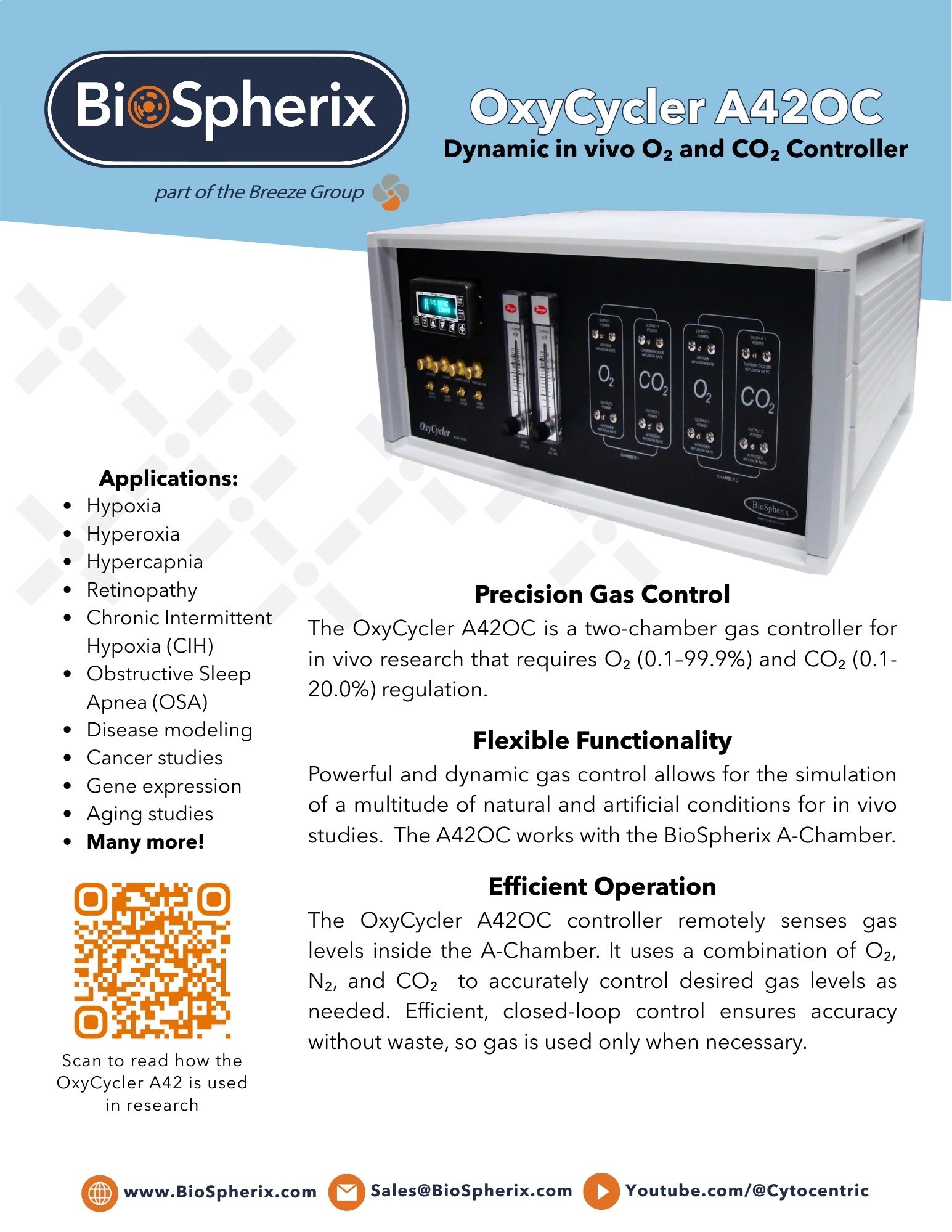
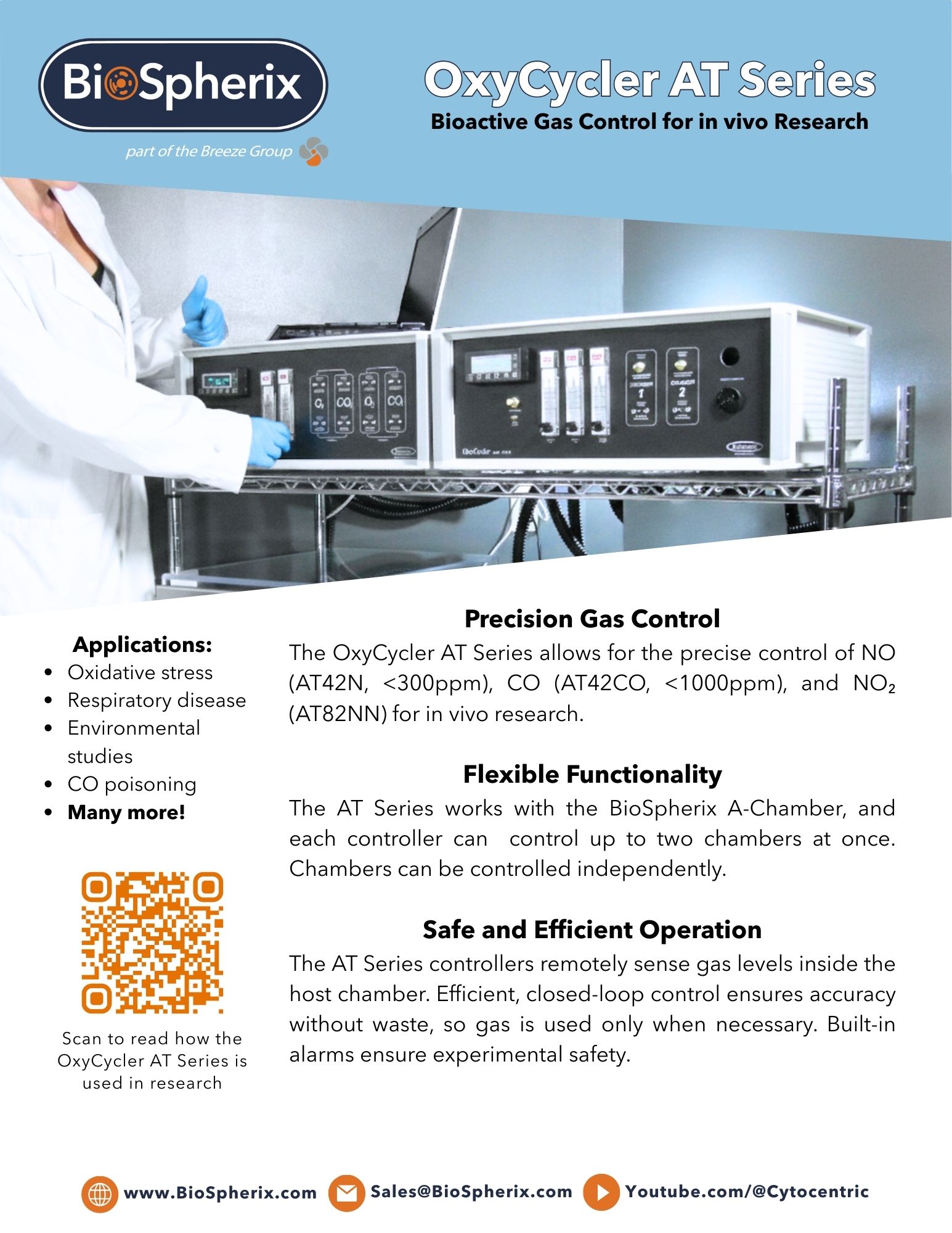
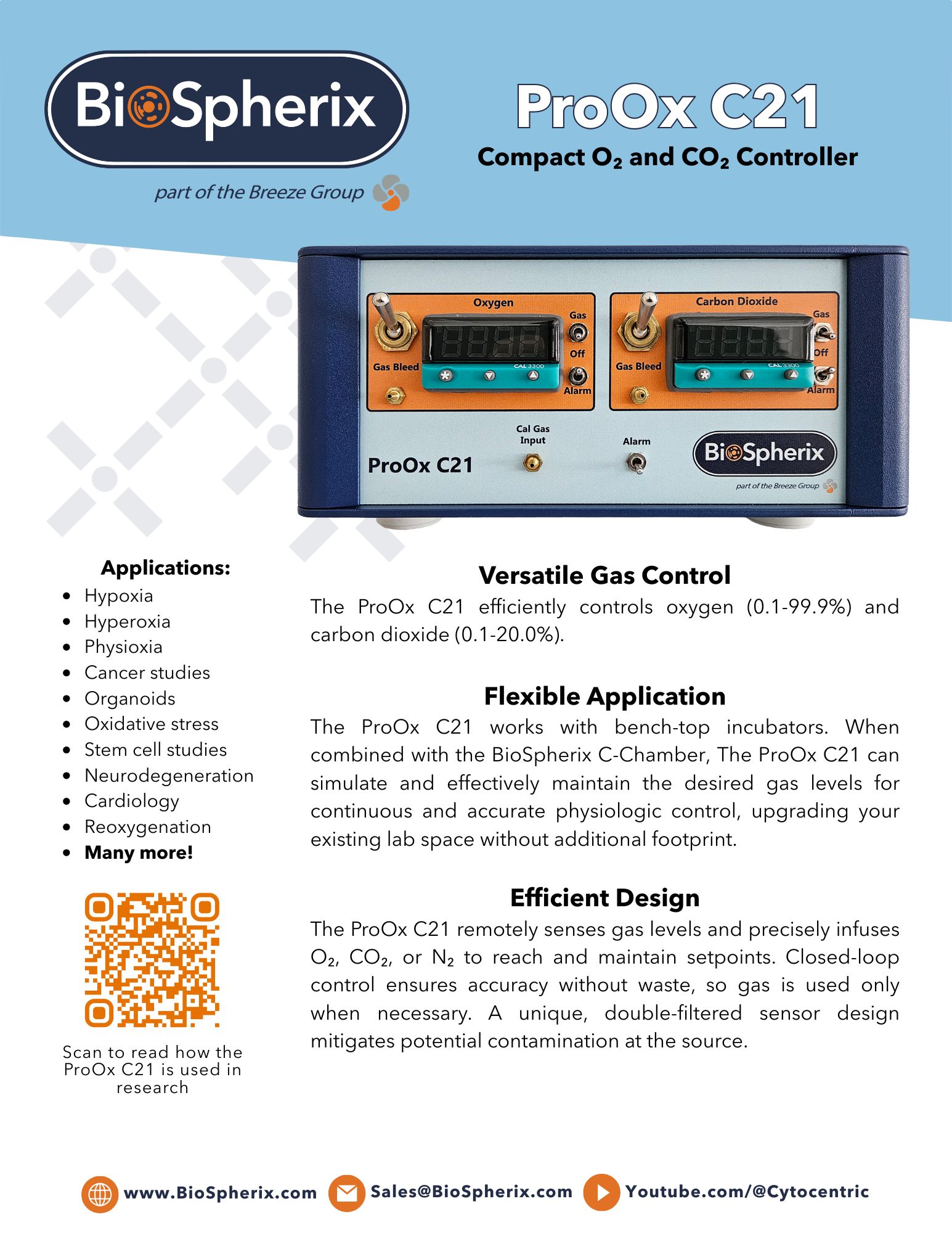
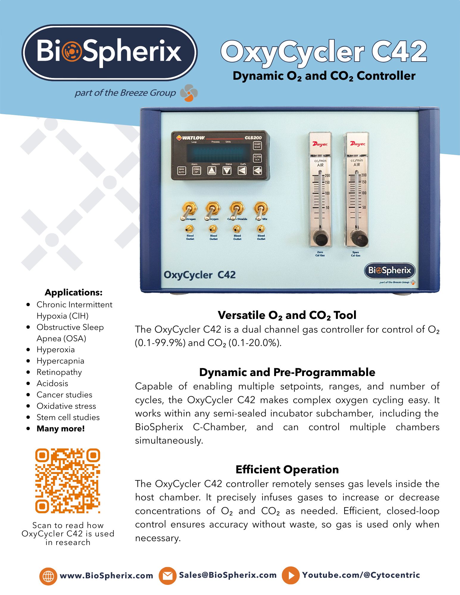
Environmental Controllers
Measure and adjust experimental parameters with ease

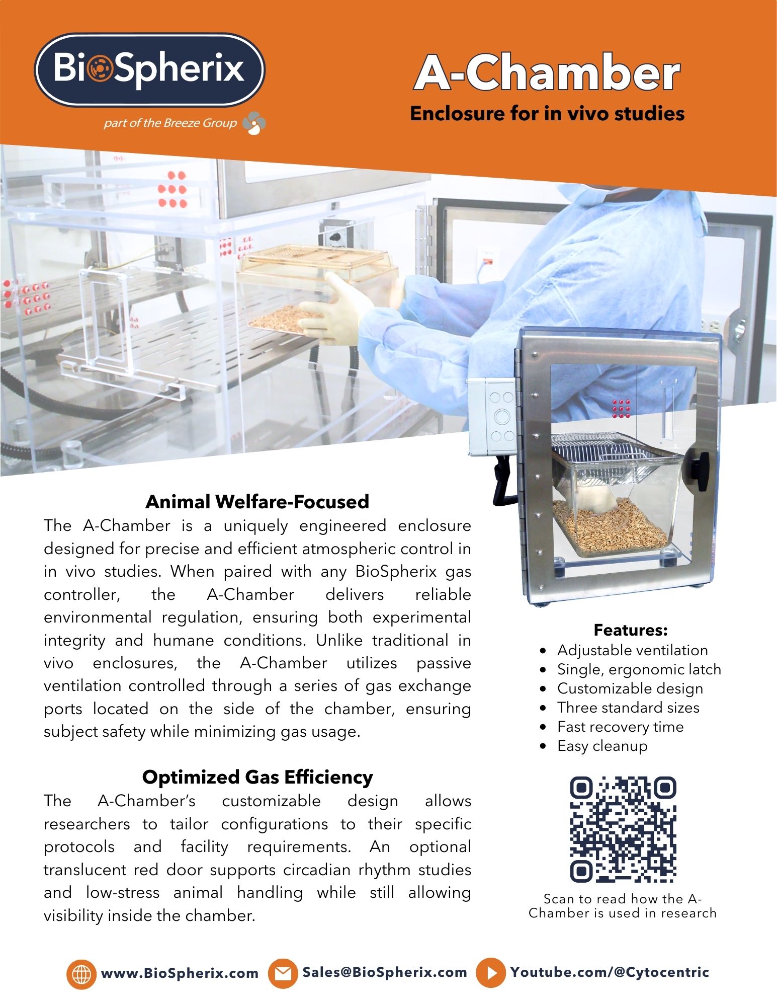
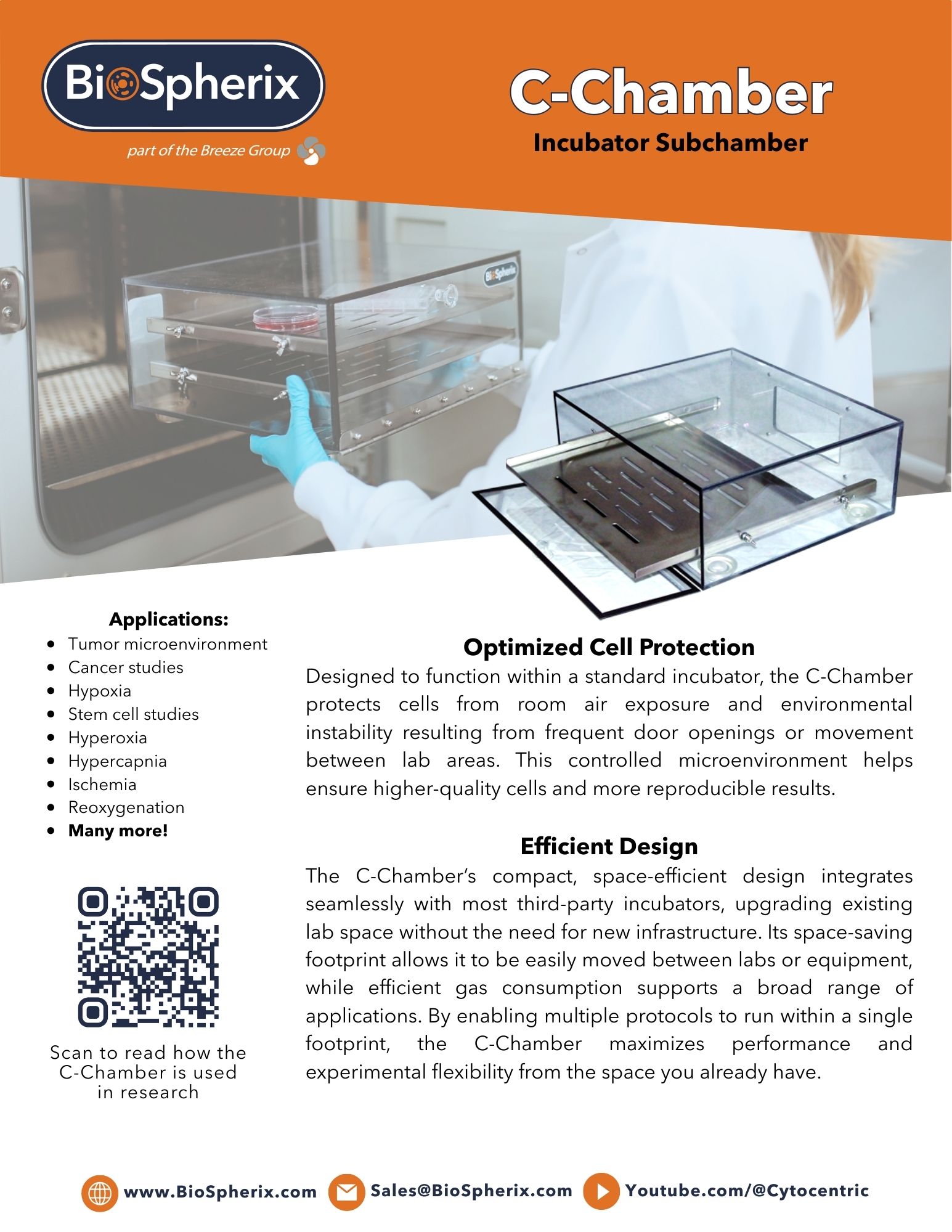
Chambers and Subchambers
Envelop your cells to maximize physiologic exposure

Xvivo Systems
Design a fully closed, Cytocentric® system tailored precisely to your protocol
Our experienced team of technicians and engineers are here to help you achieve the results you desire. Contact us today to make your science happen.